


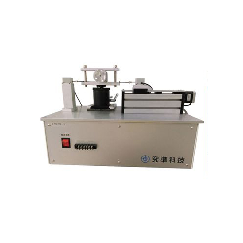
Stepper Motor Test System
Load-Sensor & Pulley Specifications:
| Model | Load Sensor | Pulley Radius (mm) | ||||
|---|---|---|---|---|---|---|
| Directly wound on the shaft *1 |
2.5mm | 5mm | 10mm | 20mm | ||
| JP-R5N | 0.5N | - | 1.25mNm | 2.5mNm | 5mNm | 10mNm |
| JP-1N | 1N | - | 2.5mNm | 5mNm | 10mNm | 20mNm |
| JP-2N | 2N | - | 5mNm | 10mNm | 20mNm | 40mNm |
| JP-5N | 5N | - | 12.5mNm | 25mNm | 50mNm | 100mNm |
| JP-10N | 10N | - | 25mNm | 50mNm | 100mNm | 200mNm |
| JP-20N | 20N | - | 50mNm | 100mNm | 200mNm | 400mNm |
Torque = Load-Sensor Rating(N) × Pulley Radius(mm)
*1: Torque will be related to motor shaft Radius.
*1: Torque will be related to motor shaft Radius.
Profile:
With the unique application of Prony (winding) braking.
It automatically obtains the full pull-in and pull-out torque curves with high accuracy.
- Pull-in torque:
The maximum torque at which the motor can start from the holding state without losing steps for a given speed - Pull-out torque:
The maximum torque at which the motor can operate without losing steps for a given loading
Advantages:
- Minimal moment of inertia of the tester:
By using the Prony method, the measurement is not affected by the inertia and the coupling loss of the test system. Especially in the Pull-in test, more to show this advantage. - Wide Measuring Range:
Six modes of sensor, to select the proper sensor and pulley,
The measuring Range is from 0.1 to 400 mNm. - Monitoring and analysis easier:
Real-time display of testing results on the screen.
Data-File can be exported to Excel format
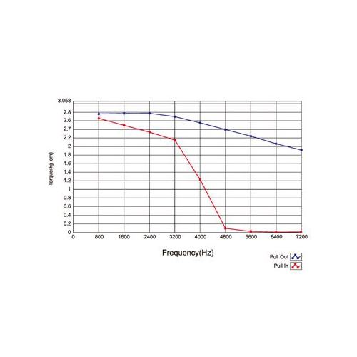
Measured Example:
- Pull-in & Pull-out Curve
- (X-axis: Frequency Y-axis: Torque)
Specifications:
| Brake | Prony braking |
|---|---|
| Load-Sensor | Six types: 0.5N, 1N, 2N, 5N, 10N, 20N |
| Sensor sensitivity | DC 2 V/ rating |
| Torque precision | Within ± 1% of torque range |
| Maximum allowable load | 200% of Sensor rating |
| Torque meas. range | T=Sensor Rating X Pulley Diameter/ 2 |
| Drive frequency range | 16-50,000 Hz |
| Drive signals | Square wave (duty 1:1), TTL-level voltage signal or open-collector signal |
| Operating System | Microsoft Windows |
| Power supply | Single-phase AC100-120V ± 10%,50/ 60 Hz |
| Single-phase AC200-240V ± 10%,50/ 60 Hz |


